In an era increasingly focused on energy efficiency and cost management, the digital power meter has become an indispensable tool for engineers, facility managers, and homeowners alike. Unlike their analog predecessors, these advanced devices provide unparalleled accuracy and a wealth of data about electrical systems. But how exactly do they achieve such precise measurements of complex parameters like energy (kWh) and power factor? This article delves deep into the core technologies—from sophisticated analog-to-digital conversion and digital signal processing (DSP) algorithms to advanced sensor integration—that empower modern digital power meters to deliver reliable and critical insights. Understanding these principles is key to optimizing energy usage, diagnosing system health, and ultimately reducing operational costs. We will unpack the science behind the screen, explaining the journey from raw electrical signals to the accurate, actionable data displayed on the meter.
Core Components of a Digital Power Meter
At its heart, a digital power meter is a sophisticated data acquisition and processing system. It transforms the raw, continuous analog signals of an electrical system into discrete, precise digital values that can be analyzed and displayed. This process is not a single-step operation but a coordinated effort between several key hardware components. Each component plays a critical role in ensuring the integrity and accuracy of the final measurement. The primary stages involve sensing the high-voltage and high-current inputs, conditioning these signals to a manageable level, converting them into the digital realm, and finally processing the vast amount of data to compute the required electrical parameters. The precision of the entire system hinges on the quality and performance of these individual components working in perfect harmony.
- Voltage and Current Sensors (Transducers): These are the frontline components that interface directly with the electrical circuit. They safely scale down high voltage and current levels to lower, isolated, and measurable values. Common types include:
- Current Transformers (CTs) for alternating current (AC) measurement.
- Shunt resistors for direct current (DC) or AC measurement.
- Potential Transformers (PTs) or voltage dividers for voltage measurement.
- Signal Conditioning Circuitry: The scaled-down signals from the sensors are often still not ideal for measurement. This stage prepares them for analog-to-digital conversion. It typically involves:
- Filtering to remove high-frequency noise that could cause measurement errors.
- Amplification to ensure the signal matches the optimal input range of the ADC.
- Analog-to-Digital Converter (ADC): This is the cornerstone of the digitization process. The ADC samples the conditioned analog signal at a very high rate, converting each sample into a binary number. The resolution (e.g., 16-bit, 24-bit) and sampling rate of the ADC are paramount determinants of the meter's overall accuracy, especially for capturing harmonic distortions.
- Digital Signal Processor (DSP) or Microcontroller (MCU): This is the "brain" of the meter. It receives the stream of digital samples from the ADC and performs complex mathematical calculations in real-time to compute values like RMS voltage, RMS current, real power, reactive power, apparent power, power factor, and energy consumption.
The Principle of Accurate Power Measurement
The fundamental goal of a power meter is to measure energy, which is the integral of power over time. In AC systems, this is complicated because voltage and current are sinusoidal and can be out of phase. A digital power meter calculates power with high precision by leveraging its high-speed sampling capability and computational power. The core principle involves instantaneously multiplying samples of voltage and current and then averaging these products over time. This method, executed millions of times per second, allows the meter to accurately capture true power, even in the presence of complex non-linear loads that cause harmonic distortions and phase shifts. This process is far superior to the methods used in electromechanical meters, which can be inaccurate under non-ideal grid conditions.
- Sampling: The ADC simultaneously samples the conditioned voltage (v[n]) and current (i[n]) signals at a rate significantly higher than the fundamental frequency (e.g., sampling at kHz rates for a 50/60 Hz system). This high sampling rate is crucial for complying with the Nyquist theorem and for accurately reconstructing the waveform, including higher-order harmonics.
- Calculation of Real Power (Watt): For each set of samples, the processor calculates the instantaneous power (p[n] = v[n] × i[n]). Real power (P), measured in watts, is then found by taking the average of all these instantaneous power samples over one cycle or a integer number of cycles.
- Calculation of RMS Values: The true Root Mean Square (RMS) value of voltage and current is calculated digitally using the formula derived from the definition of RMS. This provides an accurate measure of the effective value of the waveform, regardless of its shape.
- Calculation of Apparent and Reactive Power: Apparent power (VA) is simply the product of the RMS voltage and RMS current. Reactive power (VAR) can be calculated directly from the power triangle or by analyzing the phase shift between voltage and current waveforms.
| Measurement Type |
Calculation Method (Digital) |
Key Advantage |
| Real Power (W) |
P = (1/N) * Σ (v[n] * i[n]) for n=1 to N samples |
Accuracy even with distorted waveforms |
| RMS Voltage (V) |
V_rms = √( (1/N) * Σ (v[n]²) ) |
True effective value, not average |
| RMS Current (A) |
I_rms = √( (1/N) * Σ (i[n]²) ) |
True effective value, not average |
| Power Factor (PF) |
PF = P / (V_rms * I_rms) |
Precise measurement of phase relationship |
Demystifying Power Factor Measurement
How to measure power factor with a digital power meter is a common question, as it is a critical indicator of electrical system efficiency. Power factor (PF) is the ratio of real power (doing the actual work) to apparent power (the total power flowing in the circuit). A low power factor signifies poor utilization of electrical power, often resulting in wasted energy and potential penalties from utility companies. Analog meters measured PF using the phase displacement between zero-crossings of voltage and current waves, a method prone to error with harmonic distortion. The digital power meter, however, uses its computational prowess to derive a much more accurate and reliable value, making it the best tool for power factor correction analysis.
- Computational Method: The meter directly calculates PF using the formula derived from the definitions of real and apparent power: PF = P / (V_rms × I_rms). Since the meter has already computed highly accurate values for P, V_rms, and I_rms, the resulting PF is equally accurate.
- Phase-Angle Detection: Alternatively, the DSP can also compute the phase angle (θ) between the voltage and current fundamental waveforms using a mathematical technique called the Discrete Fourier Transform (DFT). The power factor is then given by the cosine of this phase angle (cosθ). This method is particularly useful for distinguishing between lagging and leading power factors.
- Handling Harmonics: The computational method (P / S) is considered the "true" power factor because it accurately reflects the impact of harmonic distortions on system efficiency. A waveform rich in harmonics will have a low true power factor even if the phase displacement at the fundamental frequency is minimal.
| Power Factor Type |
Description |
Common Cause |
| Displacement PF |
Cosine of the phase angle between fundamental voltage and current. |
Inductive or capacitive loads (e.g., motors, transformers). |
| Distortion PF |
Component due to harmonic currents distorting the waveform. |
Non-linear loads (e.g., SMPS, VFDs, LED drivers). |
| True PF |
The product of Displacement PF and Distortion PF. The ratio of Real Power to Apparent Power. |
A combination of phase shift and harmonic distortion. |
Advanced Features Enabled by Digital Technology
The shift from analog to digital has unlocked a suite of advanced features that extend far beyond basic measurement. The computational power of the DSP or MCU allows modern meters to perform complex analyses that were previously impossible or required separate, expensive equipment. These features transform the digital power meter from a simple metering device into a comprehensive energy management and diagnostic tool. For professionals wondering about digital power meter accuracy, these advanced capabilities are a direct result of the precise digital measurement core, which provides the reliable data necessary for sophisticated system analytics and optimization strategies.
- Harmonic Analysis: By performing a Fast Fourier Transform (FFT) on the sampled data, the meter can identify and quantify individual harmonic components in the voltage and current waveforms. This is crucial for diagnosing power quality issues.
- Data Logging and Trend Analysis: Meters can store vast amounts of historical data (e.g., energy consumption, demand, power factor) over time. This data is essential for identifying usage patterns, peak demand periods, and verifying the effectiveness of energy-saving measures.
- Communication Capabilities: Modern meters almost universally feature communication ports (e.g., RS-485, Modbus, Ethernet, Bluetooth) allowing for integration into energy monitoring systems (BMS, SCADA) for centralized, real-time monitoring and control.
- Demand Monitoring: They can calculate and record the maximum average power demand over a specific interval (e.g., 15-minute intervals), which is critical for managing electricity costs, as many utilities charge based on peak demand.
Choosing the Right Meter for Your Application
Selecting the appropriate digital power meter is not a one-size-fits-all decision. The ideal choice depends heavily on the specific application, the required accuracy class, the parameters that need to be measured, and the necessary communication features. Understanding the key specifications and how they align with your project goals is essential for a successful implementation. Whether the aim is simple sub-billing, complex power quality analysis, or integration into a building automation system, there is a meter designed for the task. This section will guide you through the critical factors to consider, helping you navigate the digital power meter installation planning process and ensure you select a device that delivers the required functionality and value.
- Accuracy Class: Defined by standards like IEC 62053-22. Common classes include 0.5S (high accuracy for utility billing) and 1.0 or 2.0 (for general purpose monitoring).
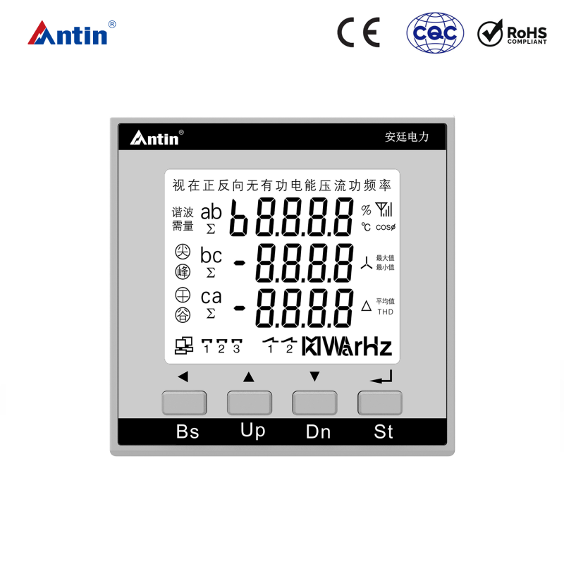
- Measured Parameters: List the essential parameters you need (e.g., kWh, kVARh, kW, PF, Vrms, Hz, THD). Ensure the meter can measure all of them.
- Communication Protocol: Match the meter's communication protocol (e.g., Modbus RTU, M-Bus, BACnet) with your existing monitoring or building management system.
- Form Factor and Installation: Consider the physical size (panel-mounted, DIN rail), CT requirements (split-core vs. solid-core), and overall ease of installation.
| Application Scenario |
Recommended Key Features |
Typical Accuracy Class |
| Utility Billing / Sub-metering |
High accuracy, pulse output, basic parameters (kWh) |
0.5S, 0.2S |
| Industrial Power Monitoring |
Advanced parameters (PF, kVAR), demand logging, communication (Modbus) |
0.5S, 1.0 |
| Power Quality Analysis |
Harmonic analysis (THD), waveform capture, data logging |
0.5, 1.0 |
| Basic Residential Monitoring |
Cost-effective, easy installation, user-friendly display |
1.0, 2.0 |
FAQ
What is the typical accuracy of a digital power meter?
The digital power meter accuracy is significantly higher than that of traditional analog meters. Accuracy is expressed as a class defined by international standards (e.g., IEC 62053). Common accuracy classes for energy measurement (kWh) are Class 0.5, Class 0.5S, Class 1, and Class 2. A Class 0.5 meter, for instance, has a maximum error of ±0.5% under specified operating conditions. Class 0.5S offers even better performance at low currents. For other parameters like power and power factor, the accuracy is usually specified separately in the datasheet and is often in the range of ±0.5% to ±1% of reading. This high level of precision is achieved through high-resolution ADCs, precise voltage and current sensors, and advanced calibration processes.
How do I install a digital power meter?
Digital power meter installation should always be performed by a qualified electrician, as it involves working with live electrical circuits. The general process involves mounting the meter in a suitable enclosure (e.g., on a DIN rail), connecting the power supply for the meter itself, and then connecting the voltage and current circuits. Voltage inputs are typically connected in parallel across the phases to be measured. Current inputs are connected via Current Transformers (CTs) which are clamped around the conductors. It is absolutely critical to observe correct polarity when wiring CTs, as incorrect wiring will lead to erroneous readings. Finally, the communication and output wires are connected according to the system design. Always consult the manufacturer's installation manual for specific instructions and wiring diagrams.
Can a digital power meter help me save on electricity bills?
Absolutely. This is one of the primary benefits of using a digital power meter. By providing detailed, accurate data on your energy consumption patterns, it empowers you to make informed decisions. You can identify which equipment or processes are the biggest energy users, track consumption during different times of the day, and monitor the impact of changes you make. Furthermore, many meters can measure parameters like power factor. A low power factor can lead to penalty charges from your utility company. By identifying this issue, you can implement power factor correction measures (e.g., installing capacitor banks) to avoid these penalties and reduce overall demand, thus lowering your bills.
What's the difference between a digital power meter and a smart meter?
While the terms are sometimes used interchangeably, there is a key distinction. A digital power meter is a broad category that refers to any meter that uses digital technology for measurement. A smart meter is a specific type of digital meter that includes advanced two-way communication capabilities, typically over a wide area network (WAN). This allows the utility company to remotely read the meter, connect/disconnect service, and receive near-real-time consumption data. While a digital meter might have communication ports for local use (e.g., Modbus for a building system), a smart meter is defined by its ability to communicate back to the utility's central system automatically.
How does a digital power meter handle harmonic distortions?
Modern digital power meters are exceptionally well-equipped to handle harmonic distortions, a common issue in modern electrical systems with non-linear loads. The high sampling rate of the ADC captures the distorted waveform in great detail. Then, the Digital Signal Processor (DSP) employs mathematical algorithms, most commonly the Fast Fourier Transform (FFT), to decompose the complex waveform into its fundamental frequency component and the individual harmonic components (e.g., 3rd, 5th, 7th harmonic). The meter can then calculate and display the Total Harmonic Distortion (THD) for voltage and current, as well as the magnitude of individual harmonics. This capability is vital for true power quality analysis and is a significant advantage over analog meters, which can give inaccurate readings under highly distorted conditions.